CAN Bus Termination Explained
CAN bus termination is required by the ISO 11898-2 standard for reliable CAN communication. This article covers why termination is necessary, how it works at the physical layer, how to measure it, and the relationship between termination, propagation delay and bit timing.
Why CAN Bus Termination Is Needed
A CAN bus is a differential signalling network. Data is transmitted as voltage differences between two wires, CANH (CAN High) and CANL (CAN Low). Like any electrical transmission line, CAN bus cables have a property called characteristic impedance, which is determined by the physical construction of the cable.
When an electrical signal travelling along a cable reaches an endpoint where the impedance changes abruptly, part of that signal's energy is reflected back along the cable. On an unterminated CAN bus, the open circuit at the cable end represents an impedance mismatch. The reflected signal travels back along the bus, superimposing back onto the signal. This can cause CAN transceivers to misinterpret bit values, leading to increased error frames and, in severe cases, nodes entering error passive or bus-off states.
By placing a resistor that matches the cable's characteristic impedance at each end of the bus, the signal energy is absorbed rather than reflected. The termination resistors also provide a path for the bus to return to the recessive state, helping the signal settle between transitions. The oscilloscope traces below show the difference this makes. Yellow is CANH and magenta is CANL.
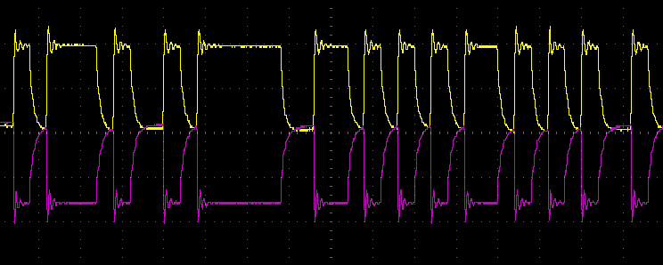
Without proper termination
Signal reflections cause visible ringing and overshoot on both CANH and CANL after each transition. The signals take time to settle, which can cause bit errors at higher baud rates.
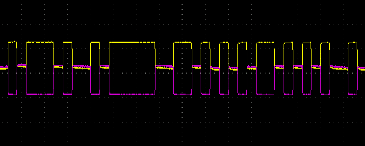
With correct termination
Both signals have clean, square transitions with minimal overshoot. The 120 Ω resistors at each end of the bus absorb the signal energy, eliminating reflections.
Why 120 Ohms?
The ISO 11898-2 standard (which defines the CAN physical layer for high-speed CAN) specifies a nominal cable characteristic impedance of 120 Ω. Compliant cables are manufactured to achieve this 120 Ω nominal impedance.
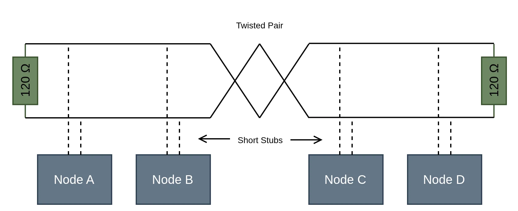
To prevent signal reflections, the termination resistor at each end of the bus must match this characteristic impedance, which is why each termination resistor is 120 Ω. Exactly two are needed, one at each physical end of the CAN bus. Intermediate nodes connected along the bus via short stubs do not have termination resistors.
Measuring Termination: 60 Ohms vs 120 Ohms
Each termination resistor is 120 Ω, but a resistance measurement across CANH and CANL on a properly terminated bus will read approximately 60 Ω, not 120 Ω. This is because the multimeter measures both 120 Ω resistors in parallel. Two 120 Ω resistors in parallel result in:
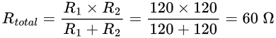
A reading of approximately 60 Ω across the bus indicates that both 120 Ω terminators are likely in place.
What Your Resistance Readings Mean
The table below summarises common resistance measurements and what they indicate about your CAN bus termination.
| Measured Resistance | Likely Condition | Action Required |
|---|---|---|
| ~60 Ω | Two 120 Ω terminators present (correct) | None - bus is properly terminated |
| ~120 Ω | Only one terminator present | Locate and install the missing terminator at the opposite end of the bus |
| Very high / open circuit | No termination present | Install 120 Ω termination resistors at both ends of the bus |
| ~40 Ω or lower | Three or more terminators present, or a low resistance fault (e.g. short) | Remove extra terminators or investigate possible short circuits |
Your reading may not be exact, as cable resistance, connector contact resistance, and the input resistance of connected CAN transceivers will shift the measured value slightly. A reading within a few ohms of 60 Ω is normal for a healthy, properly terminated bus.
How to Measure CAN Bus Termination
Multimeter
A basic check can be performed with a digital multimeter set to resistance (Ω) mode:
- Power off all devices on the CAN bus (the bus must be de-energised for an accurate resistance measurement).
- Place one multimeter probe on CANH and the other on CANL.
- Read the resistance and refer to the table above to interpret the result.
This method requires no specialist equipment other than a multimeter. However, detecting additional faults such as shorts to ground or supply requires separate measurements across CANH, CANL, ground, and power rail combinations.
Dedicated CAN Bus Diagnostic Tool
A purpose built CAN bus diagnostic tool can perform resistance measurement and additional fault detection in a single operation. The CAN Bus Debugger includes a Bus Health Scan feature that can be run on an active bus to automatically measure termination resistance and identify physical layer faults including:
- Missing or incorrect termination (displaying the measured resistance value)
- CANH and/or CANL shorted to ground
- CANH and/or CANL shorted to supply
- CANH and CANL shorted together
This is faster and more informative than a manual multimeter check. The CAN Bus Debugger displays the measured termination resistance directly on its screen alongside a plain language description of any detected faults, removing the guesswork from the diagnosis. On an active bus, it also displays min/max voltages for both CANH and CANL, allowing you to verify that signal levels are within the expected range.
The device also features an integrated programmable 120 Ω terminator that can be enabled or disabled directly from the device. This is valuable when working on a bus where one terminator is missing as you can enable the CAN Bus Debugger's internal terminator to provide the missing termination and test whether communication improves, without needing an external resistor.
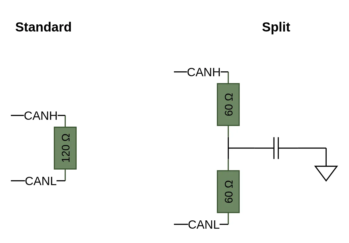
Split Termination
Standard termination uses a single 120 Ω resistor between CANH and CANL at each end of the bus. Split termination is an alternative arrangement found in some CAN networks.
In a split termination arrangement, the single 120 Ω resistor is replaced with two 60 Ω resistors connected in series. A capacitor (typically 4.7 nF to 100 nF) is connected between the midpoint of the two resistors and ground. The differential termination impedance remains 120 Ω (60 + 60), so CAN signalling is unaffected. The capacitor provides a low impedance path to ground for higher frequency common-mode noise, which can help in systems that need to meet strict electromagnetic compatibility (EMC) requirements.
When measuring a split terminated bus with a multimeter, you will still see approximately 60 Ω across CANH and CANL (assuming two split terminators), because the capacitors are open circuits at DC.
Termination, Propagation Delay and Bit Timing
Termination and propagation delay are closely related. CAN bus signals take a finite time to travel along the cable. This propagation delay depends on the cable length and the signal propagation speed in the medium (typically around 5 ns/m for standard CAN cable). The CAN bit timing scheme accounts for this delay through the propagation segment (prop_seg) of each bit time, which is sized to allow the signal to travel the full length of the bus and back before the bit is sampled.
This matters for termination because:
- Longer buses have greater propagation delay, which means reflections from poor termination have more time to distort the signal before it's sampled. Correct termination becomes more critical as bus length increases.
- Higher baud rates have shorter bit times, leaving less margin for signal settling. At 1 Mbit/s, each bit is only 1 μs long. If the propagation segment isn't correctly sized or the bus isn't properly terminated, reflections may not settle before the sample point, causing bit errors.
- The maximum bus length for a given baud rate is fundamentally limited by propagation delay. At 1 Mbit/s, the ISO 11898 specification allows a maximum bus length of approximately 40 m. At 125 Kbit/s, this extends to roughly 500 m.
The CAN Bus Debugger's CAN settings screen displays calculated propagation delay and oscillator tolerance as you configure bit timing parameters. For manual calculation and optimisation, our CAN Bit Timing Calculator lets you input your device constraints and desired baud rate to compute optimal timing settings, including the maximum propagation delay your configuration supports. This is useful when designing or validating a CAN network, as it helps you verify that your bus length and termination scheme are compatible with your chosen baud rate.
Mistakes to Avoid
Terminating every node
Only the two nodes at the physical ends of the bus should have termination resistors. Adding termination at intermediate nodes reduces the total bus resistance below 60 Ω, overloading CAN transceiver outputs and attenuating the signal. Three 120 Ω resistors in parallel give 40 Ω; four give 30 Ω. Bus communication degrades rapidly.
Using a single 60 Ω resistor instead of two 120 Ω resistors
While this produces the same total resistance on a multimeter, it defeats the purpose of termination. The resistors must be at the physical ends of the bus to absorb reflections at each endpoint. A single 60 Ω resistor placed at one location leaves the other end unterminated.
Confusing the 60 Ω and 120 Ω readings
As explained above, 60 Ω across the bus is correct (two 120 Ω in parallel). If you read 120 Ω, you may have one terminator missing.
Using stub lines that are too long
Nodes should connect to the CAN bus via short stub lines (ideally under 30 cm). Long stubs create additional impedance discontinuities that generate their own reflections, even when the bus is correctly terminated.
Measuring resistance with the bus powered on
Active CAN transceivers drive the bus, which will give inaccurate resistance readings on a multimeter. Always power off all devices before measuring termination resistance with a multimeter. Note that a dedicated CAN bus diagnostic tool like the CAN Bus Debugger performs its bus health scan using a controlled test method, so is able to measure termination directly.
Assuming termination doesn't matter at low baud rates
While the effects of missing termination are less severe at lower baud rates and shorter bus lengths, the termination resistors also play a role in returning the bus to the recessive state. Without them, the bus may not reliably transition to the recessive level, causing intermittent errors that can be difficult to diagnose.
Summary
- CAN bus termination reduces signal reflections by matching the cable's 120 Ω characteristic impedance at each end of the bus, and provides a path for the bus to return to the recessive state.
- Two 120 Ω resistors are required, one at each physical end of the bus.
- A properly terminated bus should read approximately 60 Ω when measured with a multimeter.
- A reading of 120 Ω means one terminator is likely missing. A very high reading means there is likely no termination present.
- Correct termination becomes more critical at higher baud rates and longer bus lengths, where propagation delay and signal integrity margins are tighter.